Formulation:
PROP_DESIGN does not rely upon momentum theory, Theodorsen's theory of propellers, or the Betz condition. PROP_DESIGN has no light loading limitations either. Therefore, PROP_DESIGN can easily calculate the static condition. PROP_DESIGN can also handle airfoil and blade sweep. As of January 22, 2020; PROP_DESIGN utilizes a novel solution method that I created. PROP_DESIGN executes quickly, and requires little computational resources, because it does not attempt to solve the Euler, Navier-Stokes, or Boltzmann equations.
The new formulation contains aspects of blade element theory and lifting line theory (a.k.a. vortex theory). The new formulation includes induced velocities. For educational purposes, you can also run the code without induced velocities (making it an enhanced blade element theory formulation). The affect of tip circulation has been added recently as well. Tip circulation affects can be observed when comparing ducted to unducted constant chord designs. Wake contraction/expansion can be observed when comparing straight and swept designs. Swept forward will cause wake contraction. Swept back will cause wake expansion.
The formulation is purely analytical with a few exceptions. Empirical data was used to create the atmospheric, airfoil, and stall models. The empirical data, utilized by PROP_DESIGN, is freely available online. Reputable sources were referenced:
- Atmospheric Model; United States Committee on Extension to the Standard Atmosphere (COESA)
- Airfoil Model; NACA (Predecessor of NASA)
- Stall Model; Sandia National Laboratories
The codes use the NACA 65A009 airfoil at every station. I chose this configuration because it offers good aerodynamic and structural performance. If you want to use something different, you will
have to edit and re-compile the Fortran 77 source codes. Airfoil interaction effects are not accounted for. Like propeller design codes from the past, PROP_DESIGN assumes that the airfoils are
acting independently of each other.
The airfoil analysis and CFD programs, that I have tried, have not been able to match wind tunnel data. Therefore, to use your own airfoil and stall models, I recommend wind tunnel testing. You
need to know Cd, Cl, and Cm (i.e. drag, lift, and pitching moment coefficients) for angles of attack of 0 to 90 degrees. These coefficients must be calculated for Mach numbers of .05 to 1.2 in
.05 increments. You can experiment with altitude, to see if that matters.
PROP_DESIGN was originally based on a code called PROPSY, described in the following publications:
- 'The numerical determination of circulation for a swept propeller', 1996, by Markus Tremmel
- 'Numerical Determination of Circulation for a Swept Propeller', 2001, by M. Tremmel, D. B. Taulbee, J. R. Sonnenmeier
However, over the years, I have made so many updates that PROP_DESIGN is an entirely different program. Therefore, one should not expect the results of the two codes to be the same. Rather than publish these changes via a traditional outlet, I decided to publish them online. This was done to make it easy, and free, for people to obtain them.
Limitations:
Below are the limitations of PROP_DESIGN:
- Does not have a GUI, export complete CAD models, or run in parallel; These things are outside my programming abilities. PROP_DESIGN already runs very fast using only one CPU core. So there is little reason to spend the time to re-write or modify the code to run in parallel
- Does not include nozzles or diffusers; It's easy to compute the performance of nozzles and diffusers by hand, so there was no reason to include them in PROP_DESIGN. The reference information shows how to perform these calculations
- Does not include the affect of back pressure, pitch, or yaw; It's best to avoid situations with back pressure, pitch, and/or yaw. Therefore, I did not specifically address them. I was only interested in creating the best performing propellers. Part of that involves avoiding poor operating conditions as much as possible
- Does not apply to tiltrotors, helicopters, or quadcopters; These devices operate in the worst operating conditions possible. Which is why I have no interest in them. Thrust vectoring nozzles are a much better approach. Thrust vectoring nozzles will increase efficiency, thrust to weight ratio, and safety. They will also decrease cost. The 'Recommendations' page and the 'Concepts' page give examples of thrust vectoring nozzles
- Does not apply to marine propellers or wind turbines; Although PROP_DESIGN could be modified to handle marine propellers and wind turbines, I have no interest in these devices. There are many other codes dedicated to marine propellers and wind turbines, so there is little value in expanding the focus of PROP_DESIGN
Noise Levels:
As of June 16, 2019; PROP_DESIGN can calculate aircraft propeller noise levels. There are some things to note about aircraft propeller noise. An efficient aircraft propeller is also a quiet aircraft propeller. Since you normally strive for an efficient design, there is no additional effort required to achieve a quiet design. There is a document from the past, that contains useful information, related to aircraft propeller noise. The document is based on empirical data collected by Hamilton Standard:
- 'Prediction Procedure for Near-Field and Far-Field Propeller Noise', 1977, SAE AIR1407 1977-05-01
The paper shows that, if you have an efficient design, there is only one variable left that drives noise. This variable is shaft horsepower. Noise is proportional to shaft horsepower. So, the higher the shaft horsepower is, the more noise the aircraft propeller will make. Again, from an aircraft propeller design point of view, this means that all you need to do is create an efficient design. Shaft horsepower is dictated by the size of the aircraft. The size of the aircraft is dictated by the max. payload. As an example, if you want to fly four people around, that is going to be much quieter than flying four hundred people around. There is nothing you can do about that. This is why it is a waste of time to worry about noise levels. It is more useful to minimize noise by creating an efficient design. PROP_DESIGN_OPT will automatically find the optimum geometry for any operating condition that a solution exists. So PROP_DESIGN makes it very easy to maximize fuel efficiency and minimize noise. Even so, some people require noise levels to be determined. For this reason, I have added them to PROP_DESIGN.
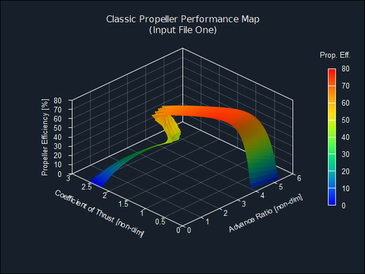
Aerodynamic Performance:
PROP_DESIGN and Gnuplot can be used to create plots which aid the understanding of aircraft propeller performance. Some of the most useful plots are shown below. The performance map was made with PROP_DESIGN_MAPS_CS. This program helps to evaluate constant speed propellers. Constant speed propellers can also be evaluated with several other codes in the download.
Aerodynamic Loads:
PROP_DESIGN outputs steady state aerodynamic loads along the span (a.k.a. the quarter chord line) of the blade. As of November 29, 2018; PROP_DESIGN now outputs the aerodynamic loads in Cartesian coordinates. This makes it a lot easier to use them in FEA software.


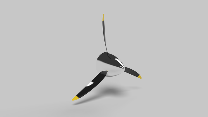
Hot Shape CAD Models:
Below are renderings of hot shape aircraft propeller and hot shape fan CAD models. The renderings are of four of the included examples; Airbus A400M, Delta Computer Case Fan, General Atomics Predator B, and the Piaggio Avanti II. These renderings should give you an idea of all the different shapes PROP_DESIGN can create.
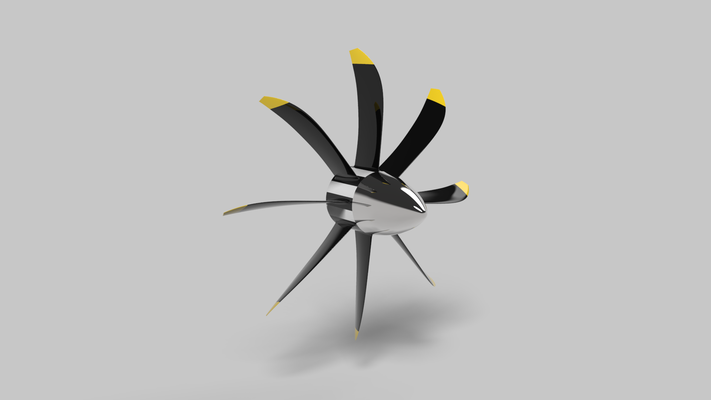
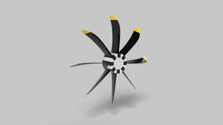
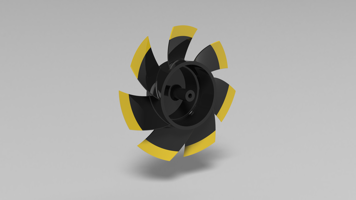


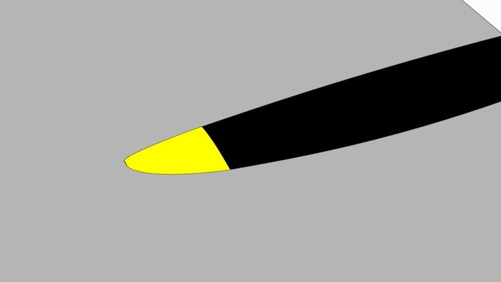
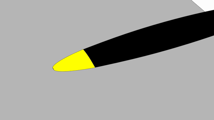
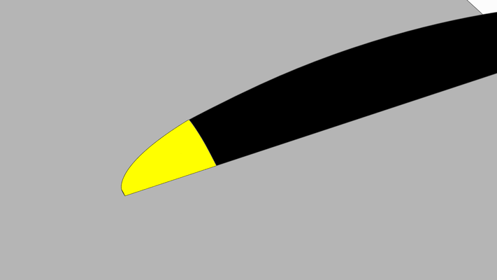
Seven different chord distribution options are available. Five of the most popular are; constant, elliptical aligned along chord / 4, elliptical aligned along chord / 2, scimitar (elliptical aligned along the trailing edge), and inverse scimitar (elliptical aligned along the leading edge). These are shown below:

Design Process:
The geometry PROP_DESIGN outputs is termed the hot shape. The hot shape is the geometry required to provide the desired aerodynamic performance. FEA is needed to find the corresponding cold
shape. Centrifugal force and aerodynamic loads will deform the cold shape into the hot shape, at a user specified shaft angular velocity. The cold shape is the geometry that should be
manufactured.
The typical aircraft propeller design process is as follows:
- Determine the required hot shape, using PROP_DESIGN (or equivalent)
- Create a hot shape CAD (computer aided design) software model, using output from PROP_DESIGN (or equivalent)
- Perform additional aerodynamic analysis, on the hot shape CAD software model, using CFD (computational fluid dynamics) software
- Perform noise analysis, on the hot shape CAD software model, using CAA (computational aeroacoustics) software
- Use FEA (finite element analysis) software to create a cold shape CAD software model that yields the desired hot shape under steady state loads
- Ensure that the cold shape CAD software model can withstand the steady and vibrational loads acting upon it, using FEA software
- Ensure that the cold shape CAD software model is not excited by flutter, using FSI (fluid structural interaction) software
- Use the cold shape CAD software model to manufacture prototype(s)
- Test prototype(s) to make sure they perform as desired
- Ensure that the final design meets all applicable regulations (ASTM, EASA, FAA, etc...)
This is an iterative procedure that is usually conducted by a number of qualified engineers. Many of these steps are performed in parallel, in order to save time and money. Many people manufacture the hot shape, this may cause you to miss your performance target. As you can imagine, this process is very complex, time consuming, and expensive. Many people have been killed due to mistakes in this process.